A friend said his Gottlieb Pioneer machine was also doing the same thing, and after going in to the player reel and tightening some screws his was working.
Oh, hopefully mine will be just as easy, right? Right? :)
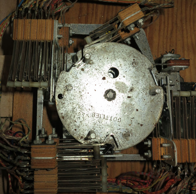
What's the player reel anyways? I had just been looking at this thing:
Why? Because it was the only thing doing any thing. This is the MOTOR. Let's take note of it for a bit because it's a fine piece of engineering.
 |
| This gives a good shot of the pole about to be triggering. In the centre you can see the pit about to be hit by the switches on the left. |
The motor turns. The notches on the metal plates activate the banks of switches surrounding it.
Here are notes from the machine schematics, and as you can see it's rotation is a somewhat intricate dance of switch-triggering through a full cycle.
Each level of plates on the motor has a different frequency for the switches, and we can see just how many wires exist from each switch, making each pulsed step a bit complex.
I barely looked at it before. I am not sure if this outer back plate has rotation independent of the center column. But the back rotates and connects with the metal switches during it's trip, triggering another set of switches.
 |
| Here we can see the contacts that spin around. I wonder if these will need cleaning? |
I was told this latches down if I remove the upper screw and HOLY SHIT, the darn thing just falls outward on a hinge. Brilliant.
Inside, we see the cogged wheels and their rotation also pulses the switches. The nodules on the hard plastic spinners are all offset so only a single switch bank fires at once.
 |
| the cogs look a touch dirty, but that's what happens when you build machines with white parts. At the bottom you can see the teeth-dense black cog for stepping through the motions. |
I checked for loose screws on the switch banks and only found 2 that weren't perfectly tight, but those only allowed a quarter twist before being snug.
I noted a contact in the switch relay had some darkish guck on it. I got out my dental tools and gently scraped that away. Then I thought, "hmmm, I hope that's residue and not actually some sort of conductive lubricant that's supposed to be there!" That's the risk of working on ANYTHING where you don't know the way it's actually SUPPOSED to be .
 |
| Here we see the stacks of switches on the left. As the nubs come round, they will get triggered in order, top to bottom, thanks to the offset of the white nubs. |
 |
| On the left are the screws I tried tightening. Not much to do there |
I also manually pushed down this solenoid and made it all step forward once, thinking it might be stuck on a final gear or something.
We can see how this solenoid works here:
 |
| the solenoid is on the bottom left. When activated, the piston to it's right pulls in towards it. It pulls the rod down, which as we can see had a pivot point, so on the other side the rod goes up. |
One solenoid pulse, one step in the machine progress. 20 pulses or so, we can get through the full cycle.
I swung the unit back up, attached the screw and pressed the power switch, hoping for full resolution and a happy game of Royal Flush.
CLICK-CLACK-CLICK! Sounds! The player unit ran through it's initialization again with noisy gusto (thanks to the backbox cover being off still,) but after that was over I was back to the pulsing playfield lights and spinning motor.
So the next step: Find out how the player reels communicates the "Hey I'm done zeroing everything up here!" signal to the next relay (whichever that one is...) and see if I can check through those.
That video video I posted last time, of that other Royal Flush owner's issue? The one where I was all "this is a different problem, since he has relays firing"? Well that was just 1 of 4 videos they posted. They did have a video where it was the exact same as I'm having now.
And in watching his video, I discovered that on power on I DID HAVE SOME RELAY ACTION! Three relays, Q+U+H, were engaging in his, and I confirmed the same in mine.
I googled his vid links and found them linked in a forum.
He seems to have received some sage advice there, but alas much of what I read is far too advanced for my current confidence. Someone said "Just poke the AX relays with a chopstick, it's finnicky" but, as above, when you don't know how it's SUPPOSED to be, best to apprehensive about just going poke poke poke.


Got here from MAACA - I love this blog!! I can't believe how much you know bout your machine already - and you say you're a novice!!
ReplyDeleteKeep us posted! I'm still looking for my first machine..... :sadface:
ha, it's do-or-die when it comes to pinball machines, so I'm trying to rocket through this learning curve. If I don't, that means I play LESS PINBALL, and that's a wholly unacceptable outcome.
ReplyDelete