Had a pinball party and tournament at my place, and lo' and behold the local master technician stopped by and volunteered to chase the gremlin out of the machine.
It was switch 37 after all: the wires were apparently backwards. Fuuuuuuuuuuuuuuuuuuck!
We had replaced the switch, but I just kept the wires the same way they were from the factory. Which was wrong.
Never assume they got it 100% on the assembly line, right?
But that was it, problem disappeared, game is 100%.
I have someone in line ready to borrow it, and they got to spend time with it on Sunday and I think they might be falling in love with Corvette. We'll see!
Showing posts with label Corvette. Show all posts
Showing posts with label Corvette. Show all posts
Monday, December 14, 2015
Friday, November 6, 2015
Corvette: done?
After tonnes of research, a thread on MAACA and a more concise thread on Pinside, the problem seems to have disappeared after reinstalling the opto board.
WHAT. THE. FUCK.
So unsatisfying, but I guess I'll take it? Might just be an intermittent issue, but I can't recreate the switch matrix issue any more. Onward and upwards?
for reference, here is the LM339 diagram:

I did one last thing to Corvette, maybe this is what fixed it?

WHAT. THE. FUCK.
So unsatisfying, but I guess I'll take it? Might just be an intermittent issue, but I can't recreate the switch matrix issue any more. Onward and upwards?
 |
| The opto board! I tested all three chips for shorts. |

I did one last thing to Corvette, maybe this is what fixed it?

 |
| Shiny new glass channel! Yes, that is what fixed the switch matrix! |
Saturday, October 24, 2015
Corvette: uh oh, I spoke to soon
Remember how I said the problem is solved? Yeah I lied.
Played a game yesterday, and the balls were being ejected in to the shooter lane due to the route 66 kickout switch triggering the trough eject switch erroneously.
But what had happened? Open up the playfield, test the switch, and sudenly NOT triggering the trough eject.
So obviously this has something to do with the other normally closed switches on the switch matrix.
Which is here:
At this point, I want to point out this great video explaining some theory of a shorted diode that can cause switch matrix issues:
Highly recommended.
So we are forming a box, consisting of:
The switch hit
The switch erroneously firing
a normally closed switch
a bad diode that is allowing current to travel both ways
I wanted to check my box theory and try activating Skid Route 66 Exit (switch 58,) but quickly learned that IT DOESN'T EXIST.
It exists in the manual all right:

But that switch does not physically exist on the game, nor on the prototype photo up at imdb.org.
So great, we have an issue that involves both columns of "normally closed" switches. I played the game and got it to the point where it was ejecting the troughs due to the ball being up in the route 66 kickout.
Turned it off, went in to switch test, and yes, pressing that switch was now triggering the Trough Eject.
What had changed?
I took the balls out of the trough, their being there or not did not change anything.
I unplugged the race track (switches 51, 52, 55 and 57) and voila, switch 57 was no longer triggering 37.
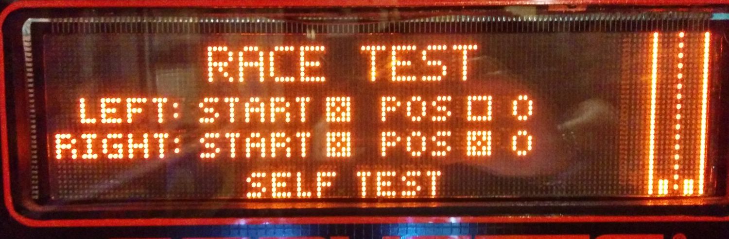
So then I put the machine in race test and started experimenting with going back to switch test with the cars at various positions, and that's where things confused me more.
There is a switch for each car to say whether they are at the starting line. (51 / 52)
Then there is 55 and 56 which have indicators, but also a number associated with position.
Sometimes the cars return to start and also have the box checked, sometimes not. Sometimes they return to 0, sometimes to position 1....
In this position, all switches reporting closed, the matrix misfire was NOT HAPPENING:

All switches... closed... solves the problem how?
I am unsure how POS relates to the number beside it.
Since we can have POS > 0 and checked, and POS > 0 and not checked!

And we can have POS not checked at zero, and POS checked at zero.

Gah. But anyways, I imagine when the box is checked it means the opto is being triggered, which would actually mean the switch is OPEN.
So if all 4 optos are triggered, then the switch matrix box can't be completed.
I will run through the logical combinations another day when I'm not so bleary eyed from lack of sleep. Needless to say, I'm closer to tracing the bad diode down. I do not think it is on the racetrack. My money is on 35 or 36.
Played a game yesterday, and the balls were being ejected in to the shooter lane due to the route 66 kickout switch triggering the trough eject switch erroneously.
But what had happened? Open up the playfield, test the switch, and sudenly NOT triggering the trough eject.
So obviously this has something to do with the other normally closed switches on the switch matrix.
Which is here:
 |
| highlight are the two switches we focus on. #57 is hit, #37 fires erroneously as well |
At this point, I want to point out this great video explaining some theory of a shorted diode that can cause switch matrix issues:
So we are forming a box, consisting of:
The switch hit
The switch erroneously firing
a normally closed switch
a bad diode that is allowing current to travel both ways
I wanted to check my box theory and try activating Skid Route 66 Exit (switch 58,) but quickly learned that IT DOESN'T EXIST.
It exists in the manual all right:

But that switch does not physically exist on the game, nor on the prototype photo up at imdb.org.
So great, we have an issue that involves both columns of "normally closed" switches. I played the game and got it to the point where it was ejecting the troughs due to the ball being up in the route 66 kickout.
Turned it off, went in to switch test, and yes, pressing that switch was now triggering the Trough Eject.
What had changed?
I took the balls out of the trough, their being there or not did not change anything.
I unplugged the race track (switches 51, 52, 55 and 57) and voila, switch 57 was no longer triggering 37.
So then I put the machine in race test and started experimenting with going back to switch test with the cars at various positions, and that's where things confused me more.
There is a switch for each car to say whether they are at the starting line. (51 / 52)
Then there is 55 and 56 which have indicators, but also a number associated with position.
Sometimes the cars return to start and also have the box checked, sometimes not. Sometimes they return to 0, sometimes to position 1....
In this position, all switches reporting closed, the matrix misfire was NOT HAPPENING:

All switches... closed... solves the problem how?
I am unsure how POS relates to the number beside it.
Since we can have POS > 0 and checked, and POS > 0 and not checked!

And we can have POS not checked at zero, and POS checked at zero.
Gah. But anyways, I imagine when the box is checked it means the opto is being triggered, which would actually mean the switch is OPEN.
So if all 4 optos are triggered, then the switch matrix box can't be completed.
I will run through the logical combinations another day when I'm not so bleary eyed from lack of sleep. Needless to say, I'm closer to tracing the bad diode down. I do not think it is on the racetrack. My money is on 35 or 36.
Thursday, October 22, 2015
Corvette: OMG DONE!
Good news, everyone! The problem has been solved.
Remember how after the big disassembly shop job there was that one hella confusing issue? I wrote about it a bit here, but I wrote about it more at pinside where I was hoping to get some help.
Short version: the Route 66 kickout switch was fubared. We replaced the microswitch + diode and now everything works.
Longer version: when the route 66 kickout switch (switch #57) was hit it sometimes also phantom triggered the Trough Eject switch (# 37)
The Trough Eject switch is above the ball trough eject, and I guess detects if balls are jammed in there on top of each other.
When activated, the game tries to clear the trough by weakly pulsing the trough upkicker, and then strongly doing so.
When the Route 66 gate opened and the ball could then could sit in the kickout, a mode like CMIYC or Drag Strip Racing would begin, all the while the game is receiving continuous notification of the Trough Switch, and so while the modes are starting the game was clearing the balls out of the trough in to the shooter lane.
That is why the trough eject was firing even if there were no balls left in the trough. It would keep firing until the Route 66 Kickout sent the ball out and around to the left inlane.
I am not expert on switch matrix issues, but testing all of the other switches in the rows and columns there was no other bleed through, just hitting the Route 66 kickout switch mistakingly triggered that other switch.
So a new switch and diode was put in, problem solved.
More rambles: My first instincts with this was the optos. This never happened before shopping the game, and happened immediately after the game got back together. I then noticed I hadn't plugged the route 66 ramp opto connector in, and in the next game, everythiung was fine.
THIS WAS A TOTAL COINCIDENCE. The switch matrix problem was intermittent, probably due to the switch not being attached properly behind the rear wall, and sometimes getting stuck.
Lesson learned: Always check everything behind the back wall of a game as well.
The issue became crystal clear when, with the game on but not Started, touching that back switch causes the trough to kick. So obviously then it was a utility function, and not indeed the gameplay code getting confused in any matter.
Good riddance, persnickety problem!
Oh, and the back gate of the LT5 wasn't raising. Why not? The spring wasn't connected. Again, another solenoid sticking out the back.
Time to PLAY.
Remember how after the big disassembly shop job there was that one hella confusing issue? I wrote about it a bit here, but I wrote about it more at pinside where I was hoping to get some help.
Short version: the Route 66 kickout switch was fubared. We replaced the microswitch + diode and now everything works.
 |
| Route 66 kickout assembly: switch and solenoid kicker |
 |
| From the back, behind the rear wall on the playfield. You'll note a missing screw, which probably didn't help. |
Longer version: when the route 66 kickout switch (switch #57) was hit it sometimes also phantom triggered the Trough Eject switch (# 37)
The Trough Eject switch is above the ball trough eject, and I guess detects if balls are jammed in there on top of each other.
When activated, the game tries to clear the trough by weakly pulsing the trough upkicker, and then strongly doing so.
When the Route 66 gate opened and the ball could then could sit in the kickout, a mode like CMIYC or Drag Strip Racing would begin, all the while the game is receiving continuous notification of the Trough Switch, and so while the modes are starting the game was clearing the balls out of the trough in to the shooter lane.
That is why the trough eject was firing even if there were no balls left in the trough. It would keep firing until the Route 66 Kickout sent the ball out and around to the left inlane.
I am not expert on switch matrix issues, but testing all of the other switches in the rows and columns there was no other bleed through, just hitting the Route 66 kickout switch mistakingly triggered that other switch.
So a new switch and diode was put in, problem solved.
 |
| Old switch and diode. |
More rambles: My first instincts with this was the optos. This never happened before shopping the game, and happened immediately after the game got back together. I then noticed I hadn't plugged the route 66 ramp opto connector in, and in the next game, everythiung was fine.
THIS WAS A TOTAL COINCIDENCE. The switch matrix problem was intermittent, probably due to the switch not being attached properly behind the rear wall, and sometimes getting stuck.
Lesson learned: Always check everything behind the back wall of a game as well.
The issue became crystal clear when, with the game on but not Started, touching that back switch causes the trough to kick. So obviously then it was a utility function, and not indeed the gameplay code getting confused in any matter.
Good riddance, persnickety problem!
 |
| Trough opto board. Notice the upper right LED is labeled JAM. This is because the designers are HUGE Space Jam fans and that is for slamming a nasty dunk. |
Oh, and the back gate of the LT5 wasn't raising. Why not? The spring wasn't connected. Again, another solenoid sticking out the back.
Time to PLAY.
Saturday, September 26, 2015
Corvette: kickback, optos, light socket
Now that I have the parts I ordered to the Ottawa Pinball show, it's time to get back to work!
There are a few little things to do on Corvette.
first was replacing the kickback plunger with a new one, plus cleaning that general area.
The kickback wasn't struggling, but I figured with the plastic bit crumbling away, time to replace it.
I also got a bunch of spare 555 bulb twist-and-lock sockets. One under the playfield had snapped, so now I have replacements.
This still leaves me with 2 issues to figure out:
Modes started up the right ramp (CMIYC and Drag Race,) sometimes eject balls in to the shooter lane at the start of the mode. CMIYC, multiball is only when you win [which is hard,] and while the drag race is easy, the balls should only be ejected at the end of it.
Since replacing the LT5 ramp, the lock kickout sometimes struggles, and I can't tell what's different.
For the right ramp I thought maybe the opto was dirty, and I was at least correct that there was dirty there.
After the cleaning, no change in behaviour. still the occasional misfires. I have no idea if has anything to do with this opto, but I do know that when I did not have it plugged in after rebuilding the playfield, it would ALWAYS behave in the wonky manner.
Intermittent problems are the WORST.
There are a few little things to do on Corvette.
first was replacing the kickback plunger with a new one, plus cleaning that general area.
 |
| no fear, i took this assembly out and cleaned everything. |
 |
| old kickback vs new one |
I also got a bunch of spare 555 bulb twist-and-lock sockets. One under the playfield had snapped, so now I have replacements.
This still leaves me with 2 issues to figure out:
Modes started up the right ramp (CMIYC and Drag Race,) sometimes eject balls in to the shooter lane at the start of the mode. CMIYC, multiball is only when you win [which is hard,] and while the drag race is easy, the balls should only be ejected at the end of it.
Since replacing the LT5 ramp, the lock kickout sometimes struggles, and I can't tell what's different.
For the right ramp I thought maybe the opto was dirty, and I was at least correct that there was dirty there.
 |
| this is the plate with the optos |
 |
| the gunk that had been wiped off |
Intermittent problems are the WORST.
Wednesday, July 29, 2015
Numerous fixes!
A quick summary of a few things that got fixed:
Eight Ball Deluxe had the Game Over lights stuck ON in the backglass. HAD.
I had people over for the Pinball Women Ottawa group I run, and after a night of playing, the next day I noticed that suddenly the Game Over was behaving.
If it was locked on, I was sure a bad transistor, and had one ready to replace it, but welp, it's working!
For all the dickheads out there that whine whine whine about women in pinball: FUCK. YOU.
What we witnessed was the magic powers of women playing pinball: shit just randomly fixes itself, apparently.
Take that, meninists.
Oh, and I had also re-adjusted the upper plastics above the 8-ball target. Now with tighter alignment, shots don't fly by the Bonus Collect hole and in to the rollovers. Very important for collecting bonus on hard shots! It is devastating if you were shooting for that collect and the ball didn't stick in.
Corvette!
Small issue with the ball sitting on the LT5 gate and not falling in to the lock. Expanded the hole on that new LT5 upwards ever so slightly, and now the alignment is far better and the ball rolls down appropriately.
Sinbad!
While playing the game would stall on ball reset and say to check coil 7 (thanks, Pascal board!)
But it was intermittent. I'd check it, look for cracked solder, but all was good. On power up, game would reset fine and you could play for a while until the error arose again.
The problem turned out to be the fuse: It wasn't blown, but one side's metal part had cracked / come loose. So when I raised the playfield, it shifted and connected again. After a few solenoid bangs under the playfield, it jiggled a bit loose and caused the error.
1 new fuse solved that issue.
Sunday, July 19, 2015
Corevette almost done!
Corvette is all back together and I can play it again! weeeeeeee
So much was put in to it:
New LT5 ramp
Cliffy on the Pit hole
Cliffy on the left side of Route 66 ramp
Cliffy on the shooter lane
New bushings + sleeves for each flipper
new rubber set
new slingshot plastics
new engine wires
full LEDs
new balls
It also had a new DMD put in just before I received it, so that is all lovely too.
And one caveat is that I didn't get a new sleeve in to the right flipper, but ah well, that coil can be replaced eventually.
With the new LT5 ramp in place, a number of problems arose that required tweaking:
The rear gate would go up and wedge in that position, requiring bending and spring tweaking to ensure it didn't rise too high.
The ball sometimes would rest on the gate and not fall in to the lock! Ack. Adjustment to the gate required.
The balls were having trouble ejecting from the lock when more than 1 was in there...
All seem fixed now.
The most serious post-assembly problem was the machine getting confused and when Catch Me If You Can started, 2 balls were ejected in to the shooter lane. And the machine knew this was happening, it wasn't so confused as to end your ball when one drained...
Normal behaviour is that if you finish CMIYC, one ball should be ejected in to the shooter lane for a 2 ball multiball.
Turns out I had missed re-connecting the route 66 ramp opto. Not sure how the game was trying to compensate, but it seemed the problem went away after reconnection. Well, almost. Last night when CMIYC started one extra ball was launched in to the shooter lane...
More investigation and testing required! Consistent problems, I can deal. Intermittent problems? UGGGGGHH
More things done?
Reattached the tilt bob
Fixed the operator buttons at the front
Tightened the bolts for the playfield pivots...
The end of the VUK wireform got resoldered back in to place... (I sent that one out...)
One benefit of the new bushings + flipper rebuild was that now there is less of a bounce coming down the inlanes and hitting the flippers. It's not perfect, but I really don't think it'll ever be perfectly smooth, AND do so while sustaining the beating that gameplay gives it.
What's left?
Well, I guess just testing (CMIYC) and tweaking (gates around the LT5).
And of course, just PLAYING and trying to beat that high score.
(aaaaand maybe lending it out. I've had no shortage of offers from people that want to borrow it for a while. They are not super common in the pinball communities around here.)
So much was put in to it:
New LT5 ramp
Cliffy on the Pit hole
Cliffy on the left side of Route 66 ramp
Cliffy on the shooter lane
New bushings + sleeves for each flipper
new rubber set
new slingshot plastics
new engine wires
full LEDs
new balls
It also had a new DMD put in just before I received it, so that is all lovely too.
And one caveat is that I didn't get a new sleeve in to the right flipper, but ah well, that coil can be replaced eventually.
With the new LT5 ramp in place, a number of problems arose that required tweaking:
The rear gate would go up and wedge in that position, requiring bending and spring tweaking to ensure it didn't rise too high.
The ball sometimes would rest on the gate and not fall in to the lock! Ack. Adjustment to the gate required.
The balls were having trouble ejecting from the lock when more than 1 was in there...
All seem fixed now.
The most serious post-assembly problem was the machine getting confused and when Catch Me If You Can started, 2 balls were ejected in to the shooter lane. And the machine knew this was happening, it wasn't so confused as to end your ball when one drained...
Normal behaviour is that if you finish CMIYC, one ball should be ejected in to the shooter lane for a 2 ball multiball.
Turns out I had missed re-connecting the route 66 ramp opto. Not sure how the game was trying to compensate, but it seemed the problem went away after reconnection. Well, almost. Last night when CMIYC started one extra ball was launched in to the shooter lane...
More investigation and testing required! Consistent problems, I can deal. Intermittent problems? UGGGGGHH
More things done?
Reattached the tilt bob
Fixed the operator buttons at the front
Tightened the bolts for the playfield pivots...
The end of the VUK wireform got resoldered back in to place... (I sent that one out...)
 |
| this pin was the issue for the operator buttons panel at the front. |
One benefit of the new bushings + flipper rebuild was that now there is less of a bounce coming down the inlanes and hitting the flippers. It's not perfect, but I really don't think it'll ever be perfectly smooth, AND do so while sustaining the beating that gameplay gives it.
 |
| good enough! |
What's left?
Well, I guess just testing (CMIYC) and tweaking (gates around the LT5).
And of course, just PLAYING and trying to beat that high score.
(aaaaand maybe lending it out. I've had no shortage of offers from people that want to borrow it for a while. They are not super common in the pinball communities around here.)
Sunday, July 12, 2015
sprucing up the Corvette engine!
There was one glaring aesthetic problem with my Corvette machine, besides the paint on the sides:
The engine was missing the classic wires!
When I noticed that someone had reproduced them, oh happy days! Joy of joys!
But alas this was just the start of my frustrations all began.
Take a look at what I found: First, many of the grommets were missing on my engine, only 3 remained in total.
Of those 3, they weren't the right size to fit the plastic! ack.
Replacement grommets were found! And here is a snap of the specs so you too can find them easily...

The old ones pushed out readily with the point of a scissor. Old ones went in with a bit of fuss and the hard edge of a screwdriver to assist.
They're in! They're all in! Well, almost. The ends of the pipes IN NO WAY SHAPE OR FORM FIT IN TO THE PLASTIC HOLE.
no fucking way.
In lieu of drilling up the unobtainium engine plastic, I decided to leave it how you see it. Not super secure, but also not likely to fall out. It's not like anything will be hitting these, right?
ARRRRRGGGH
You know what is SO. STUPID. ??? When the wires are there on the left, the whole thing rubs against the ramp wireform akwardly.
Look at this picture on IPDB. That is the correct way? So awkward.
I am going to find a way to have them secure at the upper left and right hand corners so they duck down extra low don't pull out. But in the mean time?
This is how it will sit in the interim.
I know little about engines, but I do know you connect one hose opening to another hose opening, and that's how engines work. SCIENCE, AMIRITE?
I bet my Corvette engine is now super suped compared to any others.
Will update with the rest of repairs soon. Can't talk, playing pinball.
The engine was missing the classic wires!
When I noticed that someone had reproduced them, oh happy days! Joy of joys!
But alas this was just the start of my frustrations all began.
Take a look at what I found: First, many of the grommets were missing on my engine, only 3 remained in total.
Of those 3, they weren't the right size to fit the plastic! ack.
 |
| nope, nope and uhhhhh nope. |
Replacement grommets were found! And here is a snap of the specs so you too can find them easily...

 |
| old grommets on top, new on bottom. |
 |
| joy of joys! |
They're in! They're all in! Well, almost. The ends of the pipes IN NO WAY SHAPE OR FORM FIT IN TO THE PLASTIC HOLE.
no fucking way.
In lieu of drilling up the unobtainium engine plastic, I decided to leave it how you see it. Not super secure, but also not likely to fall out. It's not like anything will be hitting these, right?
ARRRRRGGGH
You know what is SO. STUPID. ??? When the wires are there on the left, the whole thing rubs against the ramp wireform akwardly.
Look at this picture on IPDB. That is the correct way? So awkward.
I am going to find a way to have them secure at the upper left and right hand corners so they duck down extra low don't pull out. But in the mean time?
 |
| fuck it. |
This is how it will sit in the interim.
I know little about engines, but I do know you connect one hose opening to another hose opening, and that's how engines work. SCIENCE, AMIRITE?
I bet my Corvette engine is now super suped compared to any others.
Will update with the rest of repairs soon. Can't talk, playing pinball.
Tuesday, June 30, 2015
Corvette: how to tear down the playfield (aka removing the LT5 engine unit)
In the spirit of my post about how to tear down the Baywatch playfield, I wanted to present a concise summary of how to get the playfield apart on a Corvette, with the end goal of getting the LT5 engine out.
I have a lot of pictures in my prior, less-focused post.
Step 1: remove the right racetrack. You can follow the instructions as per the "Unit Disassembly For Repair #16-9887" PDF available on the IPDB page. This race track comes off with just a few screws and connectors being removed.
Step 2: remove the left wireforms. We are kind of following along the instructions for taking out the LT5, at the very least we take off the plastic engine piece. There are a few screws around the Pit's VUK wireframe assembly, and the left wireform it is attached to connectors to the left slingshot assembly. That all comes apart and the wireframe should be easy to remove.
Step 3: remove the right wireforms. In a similar fashion, considering it is attached to the right slingshot plastic, we can fairly easily take the connected 2 right wireforms. This will involve some wiggling to get them removed from the ramp, but you should be able to finesse it.
Step 4: removing the back "race ramp" and the "route 66" ramp. This is all one giant plastic piece. First up, there is a diverter for route 66. This is held in place via a single pin beneath the playfield. The race ramp has a few screws connecting it at the back. The route 66 portion has a few connectors that need to be remove, and a few screws, including the two small screws at the ramp flap. One of the connectors feed beneath the Skid Pad ramp, so you'll have to remove the 3 screws for the Skid Pad as well (might be a bit of contortion required) in order to feed that disconnected connector through. Then the large ramp assembly should come out.
You can leave the Skid Pad ramp a bit loose as it will be required to move again when feeding that one connector back through the playfield.
Step 5: TAKE OUT THE LT5! We can get back to the provided documentation for taking out the LT5. One thing they neglect to mention is that there is a gate controlled by a solenoid that is mounted at the back of the machine. You'll need to take out the spring that attaches the solenoid to the gate, which I found a touch annoying.
As per the instructions provided by Williams, lots of connectors beneath the playfield, 2 bolts, you should be able to lift the whole thing out.
Step 6: Remove the kickback exhaust assembly. Not often needed, but while we have those left wireforms
off we can easily take apart the exhaust assembly, if needed. Meh, why not? Just a few screws. Seems kind of an anticlimax after you have that monster LT5 unit out though.
GOOD LUCK AND HAPPY PINBALL SHOP-JOBBING!
Corvette shop job has begun!
It has begun! The ginormous Corvette shop job has started, only to be interrupted for a week of vacation.
Williams released bonus service docs specifically for removing and repairing the 2 big toys, the racetrack and the LT5 engine.
In tearing down Corvette the first thing is of course the race track on the right, and this comes apart readily for relatively easy maintenance.
In tearing down Corvette the first thing is of course the race track on the right, and this comes apart readily for relatively easy maintenance.
 |
| The racetrack has one main connector at front and some easily accessible ones at the back, and minimal screws. Very easy to remove. |
But for me the big thing is getting the LT5 engine out. I
had spent about 200 on a loaded replacement ramp and was eager to get it
in.
The old ramp was busted at the entrance left side, although mostly hidden by a makeshift piece of metal, and busted at the upper right. The upper right break meant that there wasn't anything to secure the top gate to, so a prior owner had connected it to the pit stop upkicker wire frame with a cable. It was a bit messy but mostly worked.
So I started the steps for taking out the Lt5. If you check the IPDB page, there is a PDF there called "Unit Disassembly For Repair #16-9887", and it is a cool document because it has the step-by-step instructions for taking out the racetrack an the LT5. The instructions for the racetrack worked out great for me, so I thought "OK, let's get to these LT5 instructions!"
As it turns out, things weren't so straightforward for the LT5.
 |
| Here is the engine unit from below. A number of connectors to be removed, and at the top left you can see the dedicated control board. The two bolts at the top secure the whole unit to the playfield. |
 |
| With the engine plastic removed you can see the large unit. To the left you can see how it goes behind the back ramp. On the right you can see how the gate had been somewhat attached the VUK wireframe for stability. |
One step was to remove the pit upkicker wire form, but that involved removing it from the left wireform, which is connected by an inverted bolt that is nearly impossible to get to, so best take out the upkicker wireform and the attached left wireform.
 |
| Here is that annoying bolt, seen with the wireform flipped over. So annoying to remove these as installed, so I just take out both wireform parts and leave the bolt connected. |
 |
| both the left and right ramps connect to the slings, so be ready for the whole thing to need to come apart. |
 |
| One other thing the manual neglects is that you have to detach this spring that connects behind the back of the playfield. This controls the back gate on the LT5. |
One instruction was then to take 2 screws off the ramp that runs along the back. You know what? That is nowhere close to enough. You CANNOT get out the LT5 unit with the ramp along the back!
But then on close inspection, you notice that the back ramp is a single piece of plastic with the right ramp! It's a huge thing.
BUT, you cannot get that plastic going anywhere unless you take off the right wireforms, which, LUCKILY, come apart rather easily after you take down a few screws and the right sling parts.
Once loosed, both wireform parts can be wiggled out of position with a little elbow grease.
That leaves us in this position:
 |
| both wireforms have been removed |
Next up, to get the big plastic away you have to remove the diverter (in upper right) by detaching the pin underneath the playfield. There are a few connectors to also remove. One problem is one connector is fed beneath that far-right Skid Pad ramp, so you need to remove three screws to loosen that ramp to get the connector out and the major plastic assembly out.
With the major plastic ramps gone, we can FINALLY remove the LT5! (There is no reason really to remove the Skid Pad from the playfield)
 |
| LT5 unit remove, with the ramp detached from the mechanism |
 |
| closer look at the mechanism, which balances and aligns via 4 solenoids and a control board, plus optos. |
 |
| New ramp on the right with many of the pieces already transferred over. The left's entrance is broken, shielded by the makeshift piece of metal. Also that upper right post plastic is smashed off the old one. |
While we're here, best to take a moment to install a Cliffy on the pit hole:
 |
| wear all around the hole |
 |
| most of the damage is hidden by the cliffy |
What else?
One minor thing to work on was taking apart the exhaust pipe kickback, cleaning it, and adding LEDs.
Oh yeah, I was replacing all lights with LEDs as I went and here is to hoping I NEVER have to do this again! ;)
 |
| This part is really easy to access with the left wireform off. |
And one last thing I noticed, there was a tragic accident in applying the Skid Pad decals, I assume from the factory.
Alas, trying to take this off and redo it is not a job for me. This machine needs new decals on the side of the cabinet, perhaps a new decal at the back, and someone who does that can take care of this. :)
 |
| can you see the issue? |
 |
| ugggggh |
So that is how it sits!
I found that the the left up-kicker wireform had a single weld that had come loose. That has now been sent away for re-welding.
As well there are new plastic tubes for the engine, but some of the grommets are missing, so a makeshift solution for that will be required as well:
 |
| only the left hole has a the black grommet here... |
Thursday, February 5, 2015
Back to Corvette
Hey, remember this game? I haven't written much about it. Guess I've been too busy just playing it?
OK, kinda. I had tried to get in to it at one point, but lifting it up I felt one side of the playfield wasn't properly supported at the tilt axis point.
I finally got someone in to help me and they quickly found the issue: A bolt had fallen off and in to the cab. Got that properly connected and in we could go!
I had thought the "light kickback" diode needed replacement since it wasn't registering well, but that turned out to be cracked solder joint. That got fixed.
I've written about the right inlane alignment before, and this finally got fixed in a more permanent way by threading in so toothpick wood. Here is to hoping that holds!
Coming up for Corvette, I am going to have a support for the entrance gate on the LT5 fixed up. Right now it's kind of sloppily tied to the VUK wireform since the LT5 ramp is cracked.
This is and always will be a player's copy, but I will do whatever I can to have it playing as 100% as possible!
OK, kinda. I had tried to get in to it at one point, but lifting it up I felt one side of the playfield wasn't properly supported at the tilt axis point.
I finally got someone in to help me and they quickly found the issue: A bolt had fallen off and in to the cab. Got that properly connected and in we could go!
 |
| oh hey we might need that. |
 |
| ayyup, there it goes! |
I had thought the "light kickback" diode needed replacement since it wasn't registering well, but that turned out to be cracked solder joint. That got fixed.
I've written about the right inlane alignment before, and this finally got fixed in a more permanent way by threading in so toothpick wood. Here is to hoping that holds!
Coming up for Corvette, I am going to have a support for the entrance gate on the LT5 fixed up. Right now it's kind of sloppily tied to the VUK wireform since the LT5 ramp is cracked.
This is and always will be a player's copy, but I will do whatever I can to have it playing as 100% as possible!
Friday, December 12, 2014
Corvette right flipper
The right flipper on Corvette just suddenly stopped working. Since I had recently installed a new flipper button on that side, I went in to the switch test.
I found the left flipper's two switch optos were tight, but the right had a flakey second one! Reseating the cable seemed to help a bit in the switch test, but still the flipper didn't work.
I ended up removing the fliptronic board:

I cleaned the optos with windex and cleaned the board as a whole. This improved the performance in the switch edge test!
But, still flipper didn't work. Under the playfield, the solution was obvious: wire had disconnected from the flipper coil's lug. Ooops.
Lesson learned: Start at the beginning and work backwards, even if you have a hunch where you think the problem might be from.
At the very least, cleaner opto board!
I don't even think the second opto mattered at all though, since there is only a single flipper on the right side.
I found the left flipper's two switch optos were tight, but the right had a flakey second one! Reseating the cable seemed to help a bit in the switch test, but still the flipper didn't work.
I ended up removing the fliptronic board:
I cleaned the optos with windex and cleaned the board as a whole. This improved the performance in the switch edge test!
But, still flipper didn't work. Under the playfield, the solution was obvious: wire had disconnected from the flipper coil's lug. Ooops.
Lesson learned: Start at the beginning and work backwards, even if you have a hunch where you think the problem might be from.
At the very least, cleaner opto board!
I don't even think the second opto mattered at all though, since there is only a single flipper on the right side.
Wednesday, October 1, 2014
Introducing... Corvette!

I am not a car person, so the theme was a shrug for me, but then again so was Monopoly.
Now that I've played it again? I am really enjoying this game! This one might last MONTHS and MONTHS in my collection, you never know.

Much of what is wrong with this game is aesthetic. Some plastic parts missing, cracked plastics, painted cab, etc.
I fixed one thing last night and it fixed the main playing issue:
Check out the right flipper:
 |
| hard to see, but that right flipper alignment is trouble! |
The flipper is obviously misaligned, so I went beneath the playfield and was able to adjust the flipper location.
(the flipper mech looked odd: someone had replaced the proper flipper spring with a big one on the coil! uh oh, will order a proper spring. Might be best to just replace flippers...)
 |
| yeah..... pretty sure that spring isn't supposed to be there. |
After doing this, no bounce! The game is that much faster now.
 |
| now the ball flows gracefully from the right inline to the flipper |
I want to clean/replace the Light KickBack target as it often does not register on a hard direct hit.
Also will probably eventually swap in LEDs. Warm whites only, most likely, because this game looks great with dim orangey incandescants.
I also went through my now-mandatory fuse inspection. Not only were a few found to be drastically overfused, I found a few jumpered entirely:
 |
| nooooooooooooooooooo |
The scoring + rules doesn't seem to deep, but I imagine I will just be enjoying this game for a while.
Some pics of the arduous setup process my space requires:


Subscribe to:
Posts (Atom)