Well let's see, all the flippers are rebuild, entire new brackets installed to replace the 2 cracked coilstops, and oh how it plays!
Well, there was one issue: with the new resistors in place, I noticed that one was exceedingly hot! Gah touched it by accident.
It was so bad that I could turn the game on, and after 2 minutes of attract mode I could turn the game off, moisten a q-tip, and touching the resistor would cause a SIZZLE.
Based on this note at pinwiki, all signs pointed to the ICs sitting just above the resistor column. They will always be warm, but what had happened previously was that one resistor had gotten SO HOT that it had desoldered itself. Yeesh
Now with the ICs socketed and replaced, the heat levels are nominal.
All good, and ready to go. Time to get some more games in before Alien Poker leaves me on Tuesday!
(OH WHAT COULD BE COMING???)
So the moon has issues. We know this.
And if you google "apollo 13 moon magnet" you'll discover that many people also have problems.
Sorry moon, you are the weakest link.
TIME TO BLOW UP THE MOON.
moon with the blue moon ramp removed.
Based on what I've read, common things going down when the moon isn't behaving:
fuse blown (located at the far back, underneath the playfield)
transistor wonky on the moon board (under the playfield, on the right hand side, partway near the front)
moon coil issue
moon magnet issue
So quick recap:
The fuse list at the front of the manual says 4A. The schematics say 3A, and apparently there was a service bulletin (can't find it, just mentions on forums) that it should indeed be 3A SB.
What did I find under the playfield? 6A.
The transistor on my board was probably bad, the fuse didn't blow, and the magnet stayed on for long periods of time, giving a slight melt to some of the nearby plastics, melting itself a bit, and making the coil toasty.
Old magnet vs new magnet:
TAKING APART THE MOON
There are small E-Clips on either side of the moon assembly, where it rotates. Get those out of there with whatever magic you can muster.
Then use a small screw driver to remove the screws going in to the moon on the right side.
You should then be able to force the moon out of the bracket holding it. Be careful not to stress the two wires going up inside the moon and connecting to the coil.
Then the moon opens like a Kinder Egg, revealing the glorious toys: a coil and a magnet.
The magnet has a threaded hole/bum and is sitting on a screw on an internal bracket. I had to use a wrench to loosen it, but then it screws off and it and the coil are ready to be stared at in horror.
your prize inside is a fried coil and a potpourri of burnt plastic smell!
to get started, you can grab this wonderful service bulletin (#80) which includes a "theory of operation" of some of the moon board logic, as well as a great quality schematic.
(I also found another service bulletin that reminds us to change F21 in the head from a 5A to a 3A, which I did)
Magnet was changed, as the old one was smashed. Coil was changed, as the old one was crispy and shorted. It read just 0.3 ohms, while the new coil read an appropriate 4.7 ohms. There was an internal break in one of the wires to the moon, and that was fixed, providing proper continuity. And after all that? We go in to solenoid test, run MOON GRAB, and still barely any effect. Something is happening, but certainly not enough to stop the ball as it is whipping around the ramp.
I initially had some confusion about the tiny board, but I found this excellent video showing a test on the board:
This illustrates how the board itself just creates an ON/OFF condition for the moon magnet.
It is the preceding logic (which is on a board with the 7-segment display, under the playfield, under the red subway,) which controls if the board get an ON signal (which is what GRAB is,) or a 10% duty cycle ON signal (which is what the HOLD is)
We figured something was wrong on the aux board, and rebuild it with all new components. This did not solve the issue.
But one thing to note: There are two components on the moon board that are not in the schematic. Based on what I can see from others on pinside, this is a common fix that must have been done at the factory line. There is a resistor from pin 1 to 5 and a diode from pin 5 to ground.
So that board was rebuild. The board that precedes it was looked over by a tech and some solder was reheated, but nothing obvious. Still no solution.
We ran a test to verify that the magnet + coil are indeed OK: We bypassed the moon board and put 50V to the coil and the magnet + moon kicked like a mule. It was unmistakable.
Then with the board in we tested the voltage drop across the magnet: It was going 76V to 66V, so only 10V across the magnet, which is why the grab was so gosh darn weak.
(while the schematic shows +50V, I was told seeing 76V isn't out of the ordinary for the high power. An initial guess was that the transistor was out of spec at 76V, but I guess not)
At this point I am wondering if the control signal that comes in from the computer?
Or something else that is causing the voltage drop to be so inadequately small?
Had a pinball party and tournament at my place, and lo' and behold the local master technician stopped by and volunteered to chase the gremlin out of the machine.
It was switch 37 after all: the wires were apparently backwards. Fuuuuuuuuuuuuuuuuuuck!
We had replaced the switch, but I just kept the wires the same way they were from the factory. Which was wrong.
Never assume they got it 100% on the assembly line, right?
But that was it, problem disappeared, game is 100%.
I have someone in line ready to borrow it, and they got to spend time with it on Sunday and I think they might be falling in love with Corvette. We'll see!
Dirt dirt dirt dirt dirt. Apollo 13 was dirt all the way down. The playfield and ramps had an almost greasy buildup, and clear plastics were rendered opaque. I had dealt with Baywatch before, and while Apollo 13's teardown wasn't quite as convoluted, it had many more parts. Lots of pictures, lots of bins. And only a few washers left over at the (almost) end. Ooops. Critical mission: replace all lights with LEDs. this game is DARK and the shroud of filth wasn't helping. Neither were all of the blackened bulbs that had not been changed in 2 decades.
Exhibit A: this lighting board from beneath the playfield:
ewwwwww
For future reference, let's review the steps in tearing down the playfield:
Stage 1 Remove the clear protector on the bottom right, including the lander toy, whose connector has to be detached beneath the playfield. Heck, while you're at it label the connectors of, and unplug, all of the flashers. Remove the left and right return wireforms. Detach 2 connectors (switch and lights) beneath playfield, and remove the plastic moon ramp. Then remove the small plastic to the right of the moon ramp, to get access to a screw there. You can then remove right wireform that is few via the left orbit/ramp
Stage 2 Then remove all of the plastic from the left hand side and around the rocket. Then remove plastic around the right hand side, and around the moon.
At this point you will have full access to the moon assembly, if need be. And yeah we need that.
Stage 3 But I wanted to clean EVERY surface of this game, so teardown continued. The butyrate plastics around the moon were trouble, melted in to the screw posts as the moon was malfunctioning and getting wildly overheated. A mess, but with careful applications of force I was able to separate them.
The upper right orbit is covered by a metal ramp and instead of removing it I decided to remove the metal edge plate and get in and clean the playfield there from the side.
by lifting that metal plate, I could clean the orbit shot without remove the lifting ramp.
This is what I consider the bare minimum of removal to clean ALL of the playfield. And it's looking gooood
The diverter that feeds the 8-ball storage had 3 big screws connecting it to the back, and could be easily separated from the controlling solenoid.
3 bolts hold this on to the back
I added tape to this lone solenoid so that the sleeve would stay put.
I was very paranoid about the upper left corner. 8 balls are stored there, and the membrane they sit on costs $200 USD to replace. Detached the connector (CAREFUL CAREFUL) beneath the playfield. The gunk was bad on it, but I used q-tips and rubbing alcohol to clean as much as I could off of it.
The back left and right corners are grand achievements to reach. Oh so happy to remove the GI bubs from back there, get it shining, and then install LEDs.
this corner = my nemesis
Oh and can never forget under the apron!
before!
after!
Quirks! A tragic little operator hack, which I believe led to the smashing of the plastic above the moon target... Seems an operator was missing a half-height rubber for a post, and instead installed a metal spring. And affixed it via inserting a screw in to the playfield.
I was having frustration with ball rejects on the far right "mode start" hole. It's a hard enough shot to hit, but a ball going up and popping out was too much. So look what I found in there: Little bits of a smashed plastic post from the shot's entrance.
A quick glance at what cleaning the pop bumper caps can do:
Oh hey, we are STARTING TO GLOW!
I know lots of people on pinball sites have LOTS OF OPINIONS about what a shop job should include, but I reject a bunch of what they keep on their lists. All new targets? All new plastic posts? Tumble the screws shiny? Not for me. My shopping goals: - Get all targets and switches working - make sure flippers are awesome - clean all surfaces - LEDs everywhere - all new rubbers Get it working and playing 100%, get it clean, get it shiny. And preferably for a minimal cost.
Some more before and after:
dirty
dirty!!!
AHHH SO CLEAN!
You might have noticed the moon has fallen to pieces... More on that in a separate post!
At this point in the cleaning, I just now have to face my nemesis: THE UNDER PLAYFIELD SUBWAY!
We are knocking things off the list on Alien Poker.
I had some help today, and the assistance was much appreciated in fixing a problem I only recently started focusing on: The left sling (the only sling in this game) was on for some games, but off for others. Most likely a cracked solder joint or loose connector somewhere.
We took the board out and reflowed solder around the connectors and the "special solenoids" chips, and that took care of the issue.
Also put in the replacement resistors, and now all the lights are on and wonderful.
BTW, you can get amazing schematics for System 6 machines at FirePower Pinball, in their Tech Support section. All schematics can be readily downloaded.
New drop target decals added.
hullo handsomes
All of the rubbers have been changed. (well, still need a 2" one...)
The left pop bumper's light wasn't working. Want to know why?
oh wait that not's quite proper.
Installed a new light socket behind the drop targets as one there had basically crumbled.
After all that, there seems to be some issue with some of the lights not lighting properly (like the shoot again coming on) so some more investigation might be required.
After tonnes of research, a thread on MAACA and a more concise thread on Pinside, the problem seems to have disappeared after reinstalling the opto board.
WHAT. THE. FUCK.
So unsatisfying, but I guess I'll take it? Might just be an intermittent issue, but I can't recreate the switch matrix issue any more. Onward and upwards?
The opto board! I tested all three chips for shorts.
for reference, here is the LM339 diagram:
I did one last thing to Corvette, maybe this is what fixed it?
Shiny new glass channel! Yes, that is what fixed the switch matrix!
Remember how I said the problem is solved? Yeah I lied.
Played a game yesterday, and the balls were being ejected in to the shooter lane due to the route 66 kickout switch triggering the trough eject switch erroneously.
But what had happened? Open up the playfield, test the switch, and sudenly NOT triggering the trough eject.
So obviously this has something to do with the other normally closed switches on the switch matrix.
Which is here:
highlight are the two switches we focus on. #57 is hit, #37 fires erroneously as well
At this point, I want to point out this great video explaining some theory of a shorted diode that can cause switch matrix issues:
Highly recommended.
So we are forming a box, consisting of:
The switch hit
The switch erroneously firing
a normally closed switch
a bad diode that is allowing current to travel both ways
I wanted to check my box theory and try activating Skid Route 66 Exit (switch 58,) but quickly learned that IT DOESN'T EXIST.
It exists in the manual all right:
So great, we have an issue that involves both columns of "normally closed" switches. I played the game and got it to the point where it was ejecting the troughs due to the ball being up in the route 66 kickout.
Turned it off, went in to switch test, and yes, pressing that switch was now triggering the Trough Eject.
What had changed?
I took the balls out of the trough, their being there or not did not change anything.
I unplugged the race track (switches 51, 52, 55 and 57) and voila, switch 57 was no longer triggering 37.
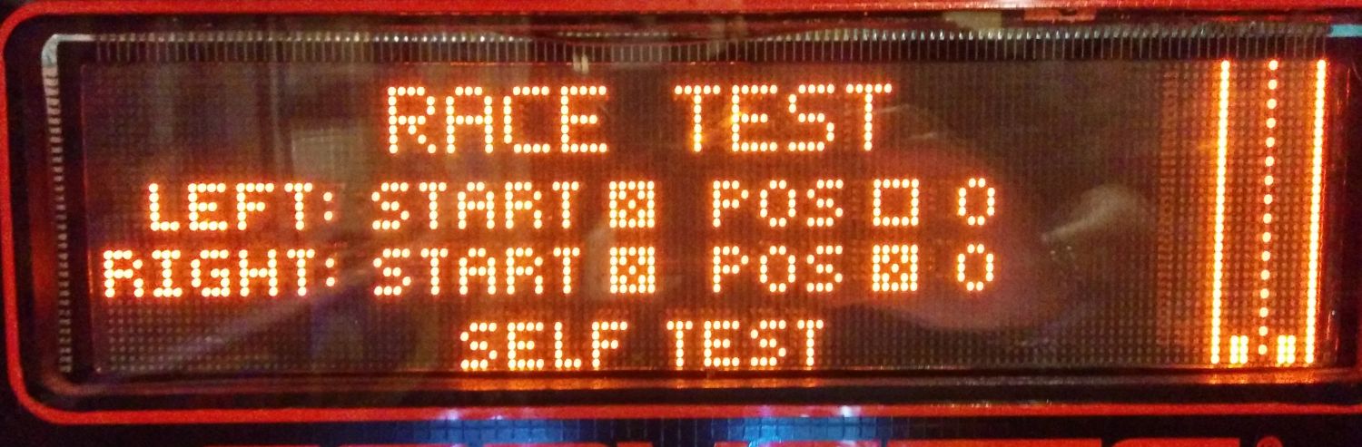
So then I put the machine in race test and started experimenting with going back to switch test with the cars at various positions, and that's where things confused me more.
There is a switch for each car to say whether they are at the starting line. (51 / 52)
Then there is 55 and 56 which have indicators, but also a number associated with position.
Sometimes the cars return to start and also have the box checked, sometimes not. Sometimes they return to 0, sometimes to position 1....
In this position, all switches reporting closed, the matrix misfire was NOT HAPPENING:
All switches... closed... solves the problem how?
I am unsure how POS relates to the number beside it.
Since we can have POS > 0 and checked, and POS > 0 and not checked!
And we can have POS not checked at zero, and POS checked at zero.
Gah. But anyways, I imagine when the box is checked it means the opto is being triggered, which would actually mean the switch is OPEN.
So if all 4 optos are triggered, then the switch matrix box can't be completed.
I will run through the logical combinations another day when I'm not so bleary eyed from lack of sleep. Needless to say, I'm closer to tracing the bad diode down. I do not think it is on the racetrack. My money is on 35 or 36.